Update: The future of this blog

Over the past few months, I have very much enjoyed making this blog. However, I am not completely satisfied with the way I have been posting things.

What I have been doing is working for a while on a project, waiting until I finish it and then writing up a post on this site and posting it. This has worked out okay for some things, but it has been restricting the frequency with which I have been able to post. More than that however, the fact that I have not really been able to post about something as I have been doing it has made me feel as though my documentation has been incomplete. I have not been able to record every thing in a very detailed manner, and in some cases I feel as though I have left entire significant steps of my process out of my posts.

To combat this, I have decided to take a whole new approach to my posting. Rather than waiting until I have completed a project to post anything about it, I will post about it as I do it. This will allow me to post more frequently, and be more detailed about what I am doing. Also, I have decided to follow a general format which will hopefully make my posts more organized. The format is pretly loose, and will allow posts to still each be unique, but will make them much easier to follow and understand. It will also make it easier for me to post about a project no matter what step of the process I am in.

To begin this, I have made posts for the next few projects I hope to complete, and will Update them as I make progress on them. As of now there is nothing more than a title and a description, but keep a look out for updates, because I will likely update the posts once every week or two, with my current progress.

Class E Solid State Tesla Coil

Description:

As an introduction to the world of solid state coiling, I have chosen to replicate Steve Ward’s class E tesla coil. The design was very simple, yet he seemed to have achieved good results, so I thought it would be a good first solid state coil.

020

Introduction:

I have always been intrigued by Tesla coils. Last summer I constructed a spark gap Tesla coil from some things I could find around my garage, and a neon sign transformer I got for about $20 at a local shop. While the it worked, the coil was much less than ideal.

The way SGTCs are built just seems very limiting, which made me want to try going solid state. Solid state Tesla coils are much more numerous in design, and the results you can get are just as numerous. There are huge diversities of spark length you can get, and plenty of designs to choose from. For a first attempt at solid state coiling I wanted something a little simpler than a half bridge. I felt Steve Ward’s class e coil was simple enough for my first attempt, so decided to build it.

I should probably explain a little bit about how Class E Tesla coils work. As you have probably heard before, Tesla coils are air cored resonant transformers. Which means when the primary circuit is oscillating at the resonant frequency of the secondary, voltages go through the roof. With spark gap Tesla coils, an LC circuit is setup with the primary to get it to oscillate at the resonant frequency of the secondary. With solid state coils, this oscillation is accomplished using electronics. The trouble is, the smaller the secondary is the higher the resonant frequency is, and with smaller coils, it can be rather difficult to use conventional driver topology to achieve the higher frequencies. To combat this, topology commonly used for radio applications is often utilized. This allows smaller coils to be driven effectively.

Design:

ClsESSTCsch

Above is the schematic of the coil, but you can also find it on Steve Ward’s website.

I guess the basic design already existed, but I decided I wanted to etch a board. I have never etched before and I thought it was about time I learned to. This circuit was simple enough that I felt comfortable trying it for my first etched board.

I drew up a schematic in eagle relatively easily. I did spend a while trying to untangle air wires on the board before I finally settled on a layout I could live with. I went with a double sided board (although in the future I think I will try to get my boards to be one sided)007

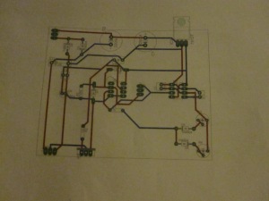
The above picture shows the basic layout. I did find one mistake on the board, and I think it is a problem with eagle’s autorouter. Pin 1 of the FET driver chip should have been grounded (and I did it in the schematic) but it wasn’t on the board. That is an easily correctable mistake though. If you want the Eagle file you can email me at Boson453@gmail.com.

011

Here is the printed layout. One of the layers is actually a mirror image so that it will be correctly lined up when placed face down on the board.

I plan to use toner transfer to make this board. The only problem is I don’t actually have a laser printer, So I will need to take the printed layout and get it copied onto photo paper somewhere. I’ll hopefully have a board etched by next week (It’s 7/14/13 now).

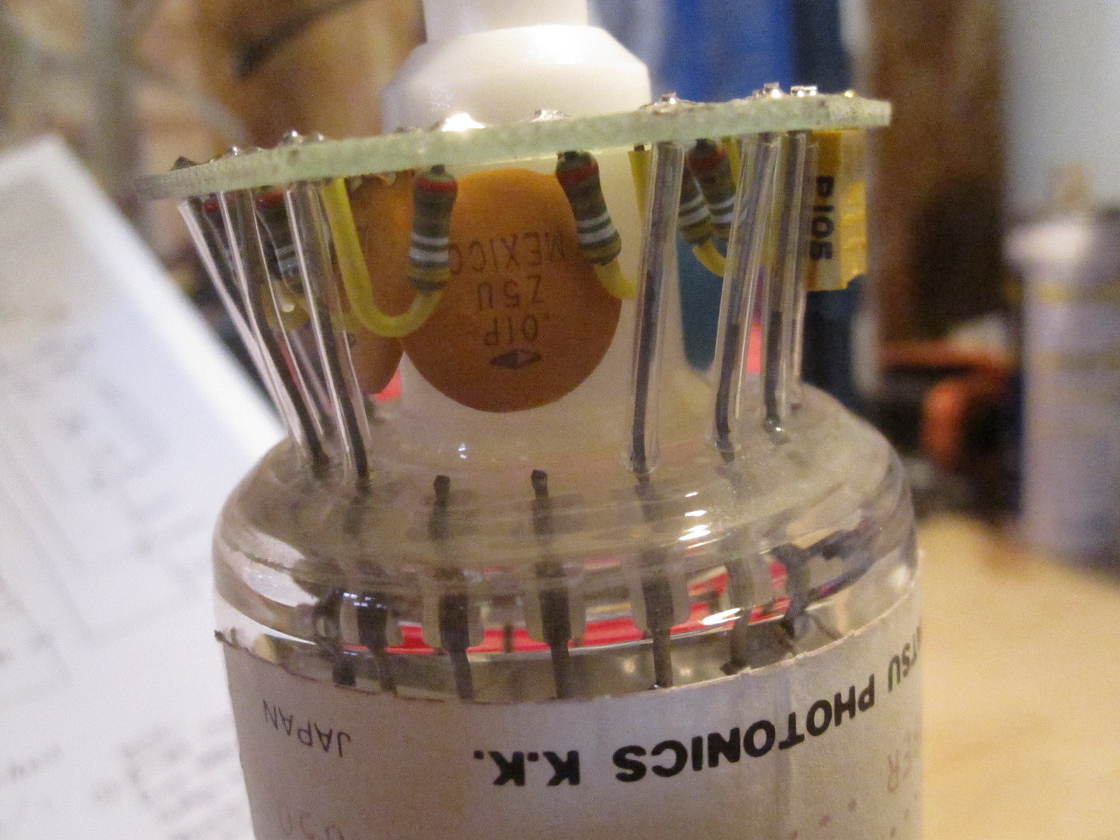
I should note that the diodes recomended in the schematic to clamp the antenna got lost (I forgot to order), so I used some point contact germanium diodes I had around. Although a 1N4148 would have worked fine, these are better suited for higher frequency applications, but mostly I think they look cool (the glass case makes them look like little vacuum tubes).

Construction:

July 19, 2013

A lot has happened. I should start from the beginning.

I had the board design as you can see above, but I do not have a laser printer. Since I planned on using toner transfer as the etching method, this was a problem. Luckily most office stores use laser printers in their copying machines so I just got the design copied onto photo paper with one.

My first attempt to transfer the toner ink failed. Luckily I had two copies made. I was much more successful the second time. After I removed the paper however, I found there were still several spots where there was quite a bit of ink missing. I tried to combat the issue by filling in the areas with sharpie. Just an FYI to anyone who may try this, it is not as reliable as you might think.

After etching the board (with ferric chloride of course) I have to say I am not terribly impressed with toner transfer. Admittedly some of the problems that came about are probably due to my lack of experience, but I still think I am going to try other methods in the future. Even so, I absolutely love etching. It for sure beats the hours spent putting something together on perfboard, and the additional hours afterwards spent finding and fixing mistakes.

004

Below is the board once populated.

022

To connect some of the off board parts/larger components, I put some pads on the board to connect to wires.  The three in the top left are for the transformer (although only two are used) , the three in the bottom left are for connections to the primary, and the three next to the bottom left go to the mosfet.

Up to this point in this project, I had kind of forgotten the reason coilers are called coilers. I had up to this point put all my thought and effort into the electronics, and kind of forgot about the coil winding part. But of course it was inevitable that I would would wrap wire around a form for a couple hours. After all, it is a Tesla coil. 

The coil was made from roughly 500 turns of 28 awg wire (8 inches tall) wrapped around a piece of 3 inch PVC (3.5 OD).

017

I threw together a little jig  made from some books to assist in wrapping the coil. While it wasn’t the sturdiest, it served my purposes fine.

018

I was pretty happy with the end result, but it wasn’t quite finished. The coil had to be coated in several layers of polyurethane to prevent further turmoil down the road when temperature and humidity begin to change (winter is coming…). If this step is skipped the wire can expand and contract causing it to cross over itself and render the coil useless.021

After varnishing, the coil doesn’t really look all that different, but it definitely is not coming unraveled any time soon.

the primary coil is still in the works. I got a 4 inch PVC coupler as the former for it and plan to wrap a few turns of 12 awg solid core wire around it. How many turns exactly is yet to be determined.

Now comes the fun part. Wiring everything together and seeing if it works. At first, it didn’t. One of my absolute least favorite things is working for a long time on a project and then turning it on for the first time only to have nothing happen.

Trouble shooting was made much easier because of the etched board, but it still took a while to figure out exactly what was going on. And to be honest I still am not quite sure of the cause of those countless anti-climactic moments proceeding the press of the power switch, but alas, I got it working.

What I do know is that there was one bad trace I didn’t catch before, and one of the capacitors had a too low voltage rating to perform its duty (it paid the ultimate price for this flaw). Also, stranded wire seems to do some weird things to the electronics, but that is mostly straightened out now.

029

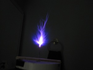
While I did get first light, there is a lot of improving to do. First, you’ll notice there is a lot of breakout/corona discharge occurring along the wire to the main breakout point. I plan to shorten the wire and give a more permanent breakout point to help prevent losses in spark length. Second, it would be nice if this didn’t stay sprawled out over my table for much longer than it needs to be, so I will be making a frame to hold everything and make it more aesthetically pleasing, portable, and in general less likely to fall apart when touched.

July 23, 2013

I have been experimenting with how many turns to include on the primary. Steve Ward said a 1.2 turn primary worked best for him, but I found a little more, closer to 1.5 turns, worked best for me. I also played around with the coupling a little bit. It worked best about 1/3 up the secondary, but the primary former I bought wasn’t that tall, so I just moved the primary as high as I could without getting arcs to the secondary.

In the schematic you’ll notice there are two potentiometers (actually trimmers on the board) that control the on and off time of the signal from the 555 chip. Since 555’s output is connected to the enable pin on the gate driver chip, the its signal actually affects the characteristics and size of the arcs. Also, you can hear the frequency from the 555 as the coil operates  since it is effectively turning the coil on and off. You could probably even get the coil to play music by tying the output of a microcontroller to the enable pin of the gate driver, but I didn’t really etch the board to allow for that addtion. Either way, I adjusted the 555 to get the longest arcs. this is a good way to adjust arc size and characteristic without actually tuning the coil.

Arcs to the secondary actually became a bigger problem than I thought. It happened several times when the primary was a little closer to the secondary or didn’t have the former between it and the secondary. Luckily none of the arcs burnt all the way through the insulation on the secondary, so it still works.

002

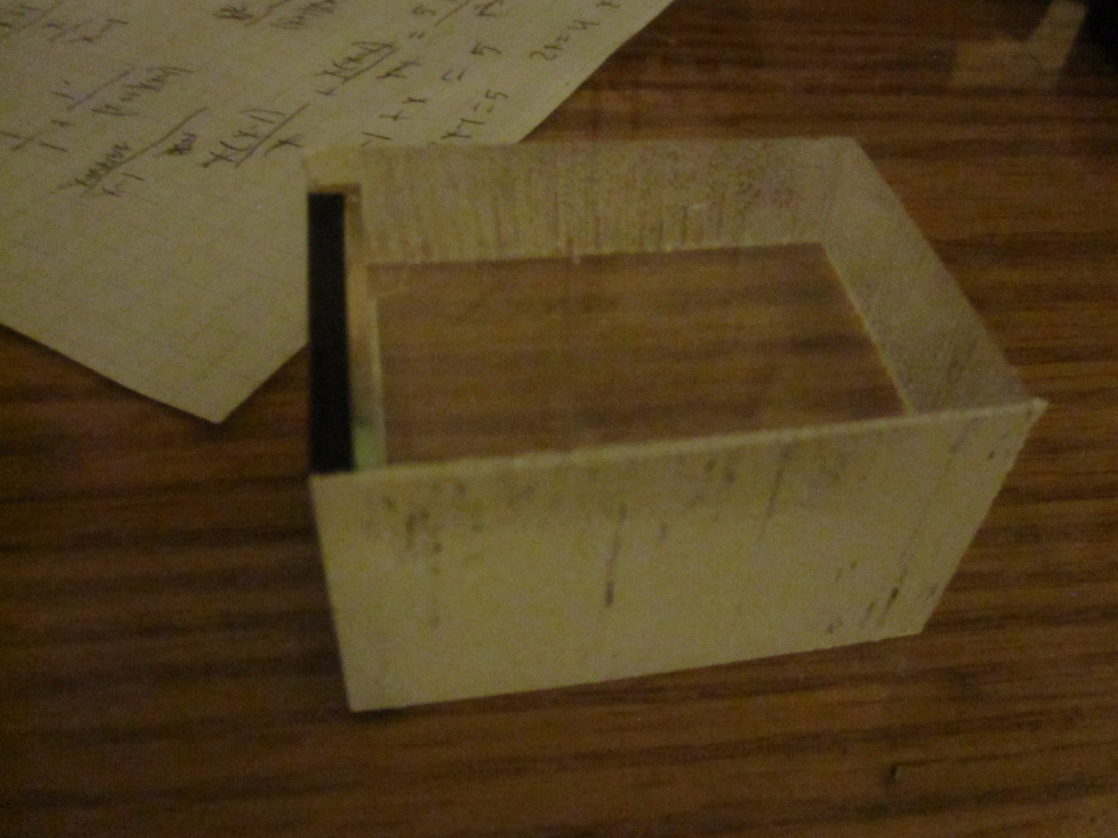
To make things look better, and to make the coil take up less space and be more portable I made a little frame to hold it. it is an 8″x8″x4″ box with open sides. the electronics are mounted to the top of the bottom face, and the primary and secondary were mounted to the top of the top face.

I also added a nail to act as a break out point. With just the wire sticking up, there were a lot of other breakout points that took away from the length of the main arc.

015 016

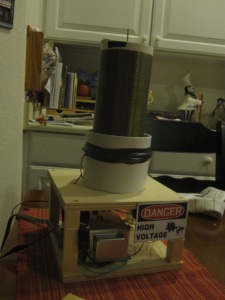
the two faces were made from 1/4″ plywood cut with a chop saw (I had to cut it from both sides), and the legs were made from four 4″ pieces of 1/2″x1/2″ wood (also cut with a chop saw). I mounted the board close to the back to with the trimmers on the edge to allow for adjustment if needed, and put the transformer in front of that. I made sure to put a fan on the front of the board to get circulation across the whole board which had a few other components (rectifiers, regulator and one of the capacitors) that were getting rather warm and either didn’t have, or had very small heat sinks. I added a danger sign just to add to the look, and then I was done.

Results:

With optimum tuning and coupling, I managed to get arcs up to 4 inches (to a grounded piece of metal), which is pretty close to the 5 inches Steve Ward managed to get.005 006

I also got a CFL bulb to light up from 1-2 feet away.

Aside from that, I managed to make a small coil that will be easy to take places for demonstrations if needed, and will be very quick (almost plug and play) to setup if I ever want to show anybody which is pretty nice.

025

Conclusion:

I managed to get good results from this coil despite it being my first solid state coiling project. It worked very reliably and is easy to adjust. (I also learned to etch circuit boards)

I am very happy with the outcome of this project, and I would say it would make an excellent first SS coiling project, or even first Tesla coil in general.

Ignition Coil Driver

Description:

Ignition coils can produce up to 60 kv AC. As an amateur scientist, I have endless uses for such a power supply. This is my design for a driver of such a coil, to be used in numerous future projects.


Introduction:


Design:


Construction:


Results:


Conclusion:

Nixie Tube Clocks

Description:

The first prototype of a product I would like to begin selling. The nixie tube clock utilizes retro vacuum tube display systems, that used to be widely used, but are now little more than a curiosity. This documents my first design for these wonderful devices.


Introduction:


Design:


Construction:


Result:


Conclusion:

Tube Amp: Marshall 9001 Preamp

Description:

My attempt to build a Marshall preamp compatible with one of my dad’s power tube amps (he commissioned me to build this). While it does include tubes as part of the amplifier, it also involves a lot of solid state circuitry, making for a highly complex build.


Introduction:


Design:


Construction:


results:


Conclusion:

Geiger Counter/ scintillation detector

Description:

A device that can measure radiation using a variety of different detection instrumentation. An adjustable high voltage supply, PMT pre amp, counting circuitry, digital display, and PC interfacing systems are included. It is compatible with many different tubes, including geiger muller tubes, PMT based scintillators, or even Boron 10 lined proportional tubes.

Introduction:

Shortly after I first made the wind bottle CRT, My dad started to get concerned about radiation. Even though I was sure there was absolutely no significant amount of radiation being produced, and even if there was it was very low energy, but I had to get quantitative experimental data. The only problem was I had nothing capable of measuring radiation. Luckily I did know someone who’s main hobby was radiography, and he agreed to help me. He brought out a Ludlum scintillation unit, and I was intrigued by it to say the least.

001 006

The unit had an a digital readout, adjustable timer for total dose counts, and adjustable power bias and amplifier settings to allow for compatibility with various different scintillation tubes.

After that, I knew I wanted to make my own unit, but I wanted to be able to detect basically any type of radiation. Pretty much the only way to do this is to use a lot of different types of tubes with it.

Design:

I decided that to start designing with the probe. I could have bought an SBM-20 very cheaply, and been done, but the first thing that I wanted to be able to do was measure background radiation, something that Geiger tubes are not the best at doing, although I wanted to return to it, I decided to start with a scintillation tube.

I chose to base the probe around the R1307 photomultiplier tube, coupled to some scintillation plastic. I chose this tube because of the large front view window, and because its peak sensitivity is at about 350 nm, that matched the scintillation plastic’s emissions. 008 012 013

The PMT has a board built into it with the divider circuit built in, which is a definite time saver. I did have to pick apart all the connections on the board myself, as no schematics were available. next is the power supply based on a CCFL inverter, and the amplifier for the PMT.

Construction:

Beginning work on the probe construction, the first thing I had to do was polish the sides of the scintillation plastic. They were very rough from machining, and needed to be more reflective for the plastic to be most effective.

To get the sides smooth I sanded the sides progressively with 60,120, and 400 grit sand paper before rubbing it with firm pressure on a brown paper bag laid flat on my work bench. Despite not having the best selection of sand paper, it worked pretty well. Not perfect, but surprisingly good.

001

Before…

003

After.

Next I had to make some modifications to the PMT’s board. I began unsoldering the resistors in the divider circuit, which actually proved pretty difficult (they were bent over the pad making desoldering difficult), and replaced them with higher value resistors, and rewired a few things using the following schematic that I found after searching the part number on my PMT.

R1307-10

005

Above is the board with the original resistors


006


The 10meg resistors (only 8 were needed).

Since the resistors were so difficult to desolder, I eventually removed the entire board to finish making all the modifications marked on the schematic.

002

Above you can see all the resistors in the divider have been replaced.

003

I made the rest of the necessary modifications and…

005

I replaced the board on the PMT which turned out to be a less than trivial task. Since I had to clip the leads to remove the board, they became too short to support the board, so I had to solder some longer leads to them prior to replacing and re soldering the board.

006

Above: The tube ready for coupling to the scintillation plastic.

007

The scintiallation plastic came with quite a bit of optical coupling compound, which I made good use of. I applied a small amount of the compound to the face of the PMT to help make a good connection to the plastic.

009

Above: I prepared the plastic by wrapping it in paper to keep the adhesive on the electrical tape from affecting the plastic, and then I wrapped both the tube and plastic with black electrical tape excluding the sides that will be coupled.

011

I then put the plastic on the PMT window, and used a gentle swirling motion to evenly spread the optical compound without creating bubbles. I used a few long pieces of tape to hold the scintillator to the PMT, and then finished wrapping both of them with black tape.

017

I decided to use a paint can to act as an enclosure for the detector because it was large enough to hold the PMT, and it was also metal which means it is easy to ground and can effectively shield the detector from electrical noise.

I wrapped the scintillation detector (now barely short enough to fit into the paint can in some recycleable packaging material digikey always uses in their shipments. I made sure to fold a little over the front of the scintillation tube to help protect it.

After drilling a hole in the lid of the can, I tightened a female BNC connector into the hole, and soldered the ground and voltage wires to it in their respective spots (ground outside of the connector and power+signal inner pin). I then taped around the connector with black tape on the inside to stop any light leaks.

018


I closed up the can, which concluded the construction of the detector.

Now It is time to work on the amplifier, power supply and counter electronics.

Results:

Conclusion:

Proving Heisenberg’s Uncertainty Principle: the work in progress

The uncertainty principle is one of the most coveted laws in quantum mechanics. Its mysterious properties have mystified physicists for decades, and you may be surprised to find out that its counter intuitive affects can be observed somewhat easily. Shine a laser through a slit. what you see projected behind it is a spot from the laser. As you close the slit, you see the spot get thinner and thinner, and you expect this to continue until the spot is too small to see, but it doesn’t. Once the slit gets very thin (on the order of a few hundredths of an inch), you see something completely unexpected. The projected light from the laser begins to fan out, getting wider and wider until the slit closes and no more light gets through.

This experiment is a somewhat common demonstration, and if you don’t believe it, try it your self. You will get the same surprising results that so many have in the past. Heisenberg came up with a very specific law to prove explain this, but how do we prove it exactly? you could measure the amount of dispersion and the width of the slit, using the unchanged output of a laser pointer, but to me this seems like it would invite a large percent of error.

I wanted to be able to prove this myself, but in a more profound way. I got thinking. Would it be possible to shine a single photon source through a slit and prove the uncertainty principle on a level of individual particles? It seemed difficult, but I actually already had a lot of the necessary materials to do this. I wanted to perform the double slit experiment with individual photons a while ago so I bought 5 ND 3.0 neutral density filters and a 1 mW laser pointer in hopes of making a single photon source. ImageImage

I intended to test the setup by letting my eyes get fully dark adapted and then try to see the characteristic uniformly bright flashes from individual photons, but I didn’t have enough patience to do it successfully. So the setup sat for a long while, until it made its way up on my “to do list.”

I reassembled the single photon source and tried to get results with my Dad’s DSLR camera (a Rebel T1i (?)).

ImageImage

Image

I wasn’t about to just shine things through slits before a control though, So I built a quick setup to hold the laser in a stationary position with an external 3.3v supply for the long exposures I made using a bulb setting on the camera with a remote shutter control.

I mounted everything on a small wood frame I made and put it in a dark exposure box.

Image

Image

After successive 1, 5, 10, 15, 30, and 60 minute exposures with both 5 and 4 filters, I couldn’t see any photons that were definitively from the laser pointer. The picture was being exposed by something however, as small spots getting more numerous with the longer exposures were visible, but it can be difinitively stated because of their dispersion that they were not from the laser pointer.

These initial tests while unsuccessful have shown me two things.

1. My “dark box” is imperfect. I am confident that no light from outside was getting it, but their was a point of weakness in that the laser’s power supply was included on the inside of the box, and it had an LED that was lit when it was on. I tried putting it in another box and covering it with a trash bag, but it is clear it was not enough. I will need to try to somehow keep it outside the box entirely to prevent exposure from anything other than the laser.

2. I did not have a good macro lens for the camera, which means that I could not focus very well on the laser which sat 12-18 inches away from the front of the lens. I didn’t realize it at first, but the fact that it was not focusing well could have been causing the individual photons to be too poorly defined to be identified. If the above point does not fix the problem I will have to wait until I have access to a better macro lens before I can continue this experiment.

To summarize, these past few weeks spent on this project have, while not being successful, shown me weaknesses in my apparatus and have shown me how I will have to proceed with the experiment. Keep an eye out for updates. I should have an update in a couple weeks or so, which will tell whether I will be able to get good results soon, or if I will have to wait longer for a better lens.

Van de Graaff Generator

About a year ago I attempted to build a Van de Graaff generator. Typically back then if I wanted to build something i would just gather what I could find for materials and then just wing it until I got something I could live with. for a lot of the things I made this ended up working okay, but it did not at all work for the VDG. There were numerous problems with belt tension, roller alignment, and motor power. After a while I simply gave up on the idea and moved on to other things.

Recently partially because of my work on my science fair project, I decided I was going to make a Van De Graaff Generator, but the right way this time. In the past any of my builds involving any kind of moving part hasn’t ended well, so I wasn’t too confident in my ability to successfully build anything mechanical going into this project. I had much more experience with designing, using tools, and putting things together in general this time, so as predicted the build went much more smoothly and was a pretty good success.

Image

I designed the VDG to be built entirely from off the shelf parts since I have no way of machining anything myself. Luckily the VDG is very simple, so this task was pretty easy.

A VDG works by utilizing a difference in triboelectric properties between the two rollers, to get a charge on a rubber belt which carries charge to and from a metal sphere at the top where the charge can build to enormous amounts. The charge is transferred to and from the belt by two metal combs or brushes at the bottom of the and top of the belt.

The first thing I made for the VDG was the rollers. I started out using some PVC end caps, but later changed the design to use bed rollers instead, because they were the perfect size and shape. To allow the rollers to spin in the VDG I attached skate bearings using a threaded rod and some nuts. I attached a pulley in a similar way to the bottom roller so It could be coupled to the motor later on.

The rollers have to be triboelectrically different, so I covered the bottom roller with Teflon tape, and the top roller with aluminium tape. Teflon and aluminum are at opposite ends of the triboelectric series, so this worked very well. The orientation of the rollers determines the polarity of the output, and with teflon on the bottom and aluminum on the top this VDG is negative.

Image

The next parts I made were the brushes. I made them by soldering straight pins on some sheet copper at regular 1/8 inch intervals. these brushes worked very well.

Image

Next I had to make the body of the generator. For this I used a piece of three inch diameter PVC pipe. I needed the rollers to be separated by about 16 inches so the belt would be stretched to about 18 inches when installed. I settled on making three holes on the bottom, two for the roller, and one to help with the installation of the brushes. For the top I decided I would drill two holes for the roller, but then cut the PVC about halfway up these holes which would leave two arcs in the PVC for the roller to sit in, but would make the belt much easier to install. To hold the sphere on the top of the body I bent a coat hanger into a V shape and glued the two legs into two small holes I drilled in the top of the PVC. The sphere would get held up by the top of the wire V.

Image

Image

Next was the belt. I would have tried to make the belts myself if I could find any fitness bands that weren’t non-latex. In the end I just ordered a  latex rubber VDG belt from Edmund Scientifics. Installing the belt was pretty straight forward. I had to do some disassembling of the bottom roller to get the bed roller part inside the PVC and the belt around it, but once I had that done I just had to pull it through the tube and put it around the top roller. The belt tension albeit not much, was enough to hold the top roller in place quite nicely.

Image

Image

To position the brushes, I nailed one brush to a small platform of scrap would and screwed into place under the bottom roller. the top roller was attached to the wire V I used to hold up the sphere.

The last thing I had to do was assemble the drive system. I was originally going to use an old drill to power the generator, but decided to use a surplus AC motor instead. The AC motor worked very well. To step up the speed a little I decided to attach a large pulley  to the motor and a smaller one to the bottom roller and use a belt to attach the two. \The ratio between the circumferences of the pulleys ended up being about 2:1 so the roller was spinning about twice as fast as the motor. This setup worked quite well.

ImageImage

To make the Sphere I used two stainless steel mixing bowls. I cut out the bottom of one with tinsnips, and taped the two together with electrical tape. I also Added electrical tape to all the sharp edges to reduce corona losses.Image

As of now The generator is putting out very strong arcs in the 4 inch to 6 inch range, but it can put out some weaker arcs that are a little over a foot long!

For more detailed instructions and a video visit instructables.com where I posted this project. You can search 350kv Van de Graaff Generator or copy this address: http://www.instructables.com/id/350kv-Van-de-Graaff-Generator/

ZVS Driver

Last summer I encountered some videos of the ZVS driver online. I had derped around with single transistor flyback drivers, but it wasn’t anything too serious. The ZVS on the other hand was promised to be the most efficient driver around, and the videos of it only supported this. I had kind of forgotten about this driver until I was browsing Mouser one day looking for some Mosfets, and thought I recognized them from somewhere. After a few google searches I found that I had indeed seen them before, on the Mazzilli ZVS driver schematic. I quickly looked around to find the other necessary components  and found that I could get enough components to make two of the drivers for under $30! After knowing that I couldn’t possibly keep myself from this wonder of electrical engineering any longer. I ordered the parts and got building. Before long I had my own ZVS driver.

001 002 004

I made sure to use thick wire for all the connections because up to 10A could be going through the circuit. I wound the 5+5 primary with 18awg enameled wire and it has worked fine. I also put a rubber pad between the wood and the bored as well as adding a power switch and some 12 awg wire for connection to the batteries on the power input terminals. I also replaced the inductor, but I have no idea of the value of either inductor that I used. Everything else has stayed pretty much the same and matches the specs recommended on the schematic.Mazzilli ZVS Flyback Driver

The ZVS is a push pull oscillator. In its purist sense it would consist of nothing more than two mosfets a capacitor and an inductor. The driver relies on the fact that no two components are exactly alike and uses small differences in the mosfets’ internal resistances and other properties to start the oscillation. The capacitor prevents the current at the primary from rising to the point where the core saturates, and the inductor prevents AC from getting back the the batteries. Other components are used as you can see though. The fast diodes prevent the fets from turning on when they shouldn’t and going suicidal. The rest of the additional components act as gate protection to make sure excessive voltage does not reach the gate of the mosfets and kill them.

In operation the capacitor and primaries form an LC circuit, so you can easily change the frequency that the driver opperates at by changing the value of the capacitor and/or the number of turns on the primary.

To power the thing, I tried to use 6v lantern batteries at first, but these are not at all designed to handle a 10A current draw. I found that with 6 of them in series the voltage would drop from about 36v to about 8v! This fact made them absolutely useless for this driver.

what you really need is a few sealed lead acid batteries. Although big and relatively expensive they can pump out some serious amps without any trouble, and are absolutely perfect for the ZVS. I started out by ordering two 12v SLABs from ebay, though I plan to get one or two more when I have some more money.004

Despite running at only 24 volts, this driver was putting out some very impressive results. I estimate the voltage is 20kv-25kv, which is decent, but the current had to have been at least 100ma! I was able to draw the arcs which started at a little over an inch to 5-6inches!008 009 010 011

The ZVS is a truly marvelous device, and I can already think of a lot of projects I would like to include it in. The only problem I have had with it so far is that it has a tendency to destroy every capacitor I use with it after a while. I originally had an MKP cap on it, but it inexplicably failed on my second day of using the driver. I bought a mica cap with the necessary ratings as a back up, but it over heated and eventually failed as well. I found another random film cap in an ATX power supply a while ago with pretty good specs so I tried it. It worked surprisingly well for about a week before it too over heated and failed. As it stands I am still looking for a suitable capacitor, but I’ll update you when I find one.

If you attempt to build the ZVS driver, always keep it on an insulating surface, and use a chicken stick! a 2 foot long piece of white (black colored pipe can indicate carbon which can become conductive) PVC should work well. Never touch a live wire of the ZVS while it is on even if it has insulation! Also make sure you always disconnect the driver from the batteries if you are going to touch anything on the driver. Power switches are convenient, but you shouldn’t entrust your life with them as it is easy for them to get turned on by mistake. Also it is just a good idea in general to have multiple checks to make sure a high voltage device is off so you don’t loose your life.

Wine bottle CRT

So some time ago I was browsing youtube when I cam across the most wonderful video I had seen up to that point. Someone had constructed an old school cold cathode electron accelerator (called CRTs or discharge tubes) out of a wine bottle and some stuff from a local hardware store. I made a mental note that I wanted to try it, but when I saw the cost of the necessary vacuum pump I kind of lost interest. a few months later or so I was looking at instructables, when I saw that Daniel Kramnik had posted instructions on how to make it. This rekindled my interest, but I still didn’t have the money to buy a pump. That summer I saved a little money and at last I had one. Also that summer I had gone to a local neon sign shop and picked up a small neon sign transformer for $20! For the vacuum port on the bottle (also acts as the cathode) both of my sources for making this recommended using a concave surface which helps focus the beam. The original video said that they had used a drawer handle and the instructable said to use a mini doorknob. I couldn’t find either at my local hardware store, so I made my own design for the vacuum port. I had previously tried to setup some kind of system for connecting my vacuum pump that could act as the standard for all of my future projects. When I bought the pump it was claimed to have both a 1/4″ and 1/2″ port on the pump. When I got it, it looked more like a 1/4″ and 1/8″ ports. This was not much of a setback however. More frustrating was that I could not find a single flared hose barb fitting at any of my local hardware stores. I have found some that will work on belljar.net, but they don’t come cheap. It’s about $10 dollars for one of them. After a while I resolved to just tighten the hose I was going to use directly onto one of the ports threads. I had a length of vinyl tubing sitting in my garage that was the right diameter, but its walls were too thin and it collapsed under vacuum. To combat this I found some 1/4″ fuel line that was strong enough to withstand the vacuum, and used a small piece of the vinyl tubing to connect the vacuum pumps port to the fuel line. Hose clamps were used on both connections and lots of teflon tape on the pumps port. For most of my experiments I simply connected the bottle to that one length of tube directly to the pump and it worked surprisingly well. I am currently working on trying to connect a thermocouple gauge tube to get vacuum readings, but am having some problems with leaks  on new connections. For most purposes the single hose connection will be fine. Image This shows how I made the connection with the hose. A flared hose barb will be used in the future. Based on my system for connecting to the pump (using the 1/4″ fuel line) I decided to just buy a whole bunch of hose barbs that fit the fuel line to connect the chamber to the hose. The hose barb size ended up being 1/8″ pipe thread to 1/4″ barb I think. To make the vacuum port on the wine bottle I used one of the hose barbs described above, a 1/8″ pipe nipple, two washers with holes that roughly fit the nipple, and some epoxy (I have tried both five minute epoxy and JB weld successfully). I started by gluing together the two washers. Once that dried I tightly threaded the hose barb onto the nipple (teflon tape is not needed because epoxy will seal it). I then put the nipple through the washers, and glued the bottom of the hose barb down taking care to leave no gaps in the bead of epoxy. I then aded more epoxy around the edges of the hose barb to ensure a good seal. once the assembly was complete I used a rather large amount of epoxy to secure the washers to the top of the bottle once again put more epoxy on the sides to fill in any gaps and get a good seal.ImageImage The vacuum port also acts as the cathode so we will not have to worry about making at least one of the electrodes. The anode however does need to be added. I found a 3/16 (I think) glass/tile spade bit at my local hardware store which was perfect for drilling a hole in the side of the bottle to allow for a wire to be put through to act as the anode. Drilling the hole is pretty strait forward. You just put the bit in your drill apply a little pressure and start drilling slowly and carefully. I found the hole can be a little difficult to start, but putting a piece of masking tape on the spot you want to drill helps keep the bit from wondering away from where you want to drill. You should probably do this before you attach the cathode/ vacuum port, because if the bottle cracks when you are drilling it is trashed and you can’t use it. Once the hole is drilled You just need to slip the wire for your anode in the hole (the shape doesn’t really matter. I’ve put it in a loop and just bent it downwards and it doesn’t really affect performance), and epoxy it in place. I used a thick layer of epoxy on top of the initial seal to help keep the anode wire from breaking from being bent around a lot (my original CRT had to be decommissioned because the anode wire broke off). Image It’s really messy, but it provides a good seal and good strain relief for the wire. The next step is to make a power supply. As a rule of thumb you want a DC power supply that can provide around 10kv. You can use higher but beyond 30kv x-ray production starts to become a concern, so you don’t want to exceed it. You can also use a lower voltage (as I did). I’m not sure what the minimum voltage required to get it to run is, but I would bet you need at least 2kv. I made my power supply by using a 6kv 30ma neon sign transformer with a microwave oven diode to rectify the AC. To find the DC voltage that is output by rectified AC you use the folling formula: Vin (1.414) = Vout. To wire up the CRT I connected one HV terminal of the NST to the cathode of the CRT, and connected the other terminal to the anode of the microwave oven diode. The cathode end of the diode connects the anode of the CRT. The low voltage terminals of the NST get connected to the hot and neutral or mains. Pay attention to the stripe on the diode which indicates the diode’s cathode when wiring up your CRT and always use wire rated for the voltages you are working with. ImageImage All that’s left to do now is fire up your pump, turn on the high voltage and watch the plasma!ImageImageImageImage Nothing happens at atmosphereic pressures because the free mean path is too small, but once your pump has been running for a while plasma begins to form as the accelerated electrons excite the gas (nitrogen) inside the tube. You will notice several features that occur with in the tube which deserve explaining. One of the first features of the plama you will experience is what’s known as a Faraday’s space, and it is the gap in plasma that starts to form at relatively low vacuum, where the collum of plama begin to separate from the cathode. This occurs because there is a higher concentration of electrons near the anode (which electrons are attracted to) than the cathode resulting in more plasma. After pump runs a little longer you will notice the plasma forming stripes. These are called striations and they occur because there are going to differences in the glass (and any other material in the tube) from one part of the tube to another resulting in a higher concentration of electrons, and therefore plasma, in some parts of the tube. These descriptions are probably over simplified, but they get the idea across. If your pump is good enough and your bottle sealed well enough, then after the striations form, the faraday’s space and striations disappear and the bottle gets filled with a uniform light blue plasma. After this happens you may notice another very interesting feature. Starting from the cathode the plasma will disappear, and be replaced with emptiness within the tube. The glass around the emptiness however will fluoresce under the bombardment of electrons, and as the vacuum increases so does this empty space until the amount of gas inside the tube is too low to facilitate cold cathode emission any longer and the tube goes dark (it is unlikely you will reach this low of vacuum with your pump). This is called the Crookes dark space and to me it is one of the most fascinating features that occurs in discharge tubes. This project was a lot of fun, and now I can tell my friends that I have built a particle accelerator! I am far from finished with CRT projects though. In the future I intend to make a CRT oscilloscope from scratch using an electron gun assembly. I also want to try an experiment that uses an old 2 inch CRT along with some other equipment to determine the charge mass ratio of the electron, just like Thomson’s third major CRT experiment. Also for those who are interested I am currently working with some professors from DU to make a more serious and more powerful particle accelerator (atom smasher) to perform experiments I hope to enter in the ISEF. Well that just about does it for this project. I encourage you to try this and have fun with it, but be very careful when dealing with high voltage and vacuum, and make sure you are not producing x-rays! Also You should probably limit the amount of time you leave this running to a minute or so to decrease the chances of something bad happening.